Difference between revisions of "ESP8266 / ESP8285"
| (27 intermediate revisions by the same user not shown) | |||
| Line 1: | Line 1: | ||
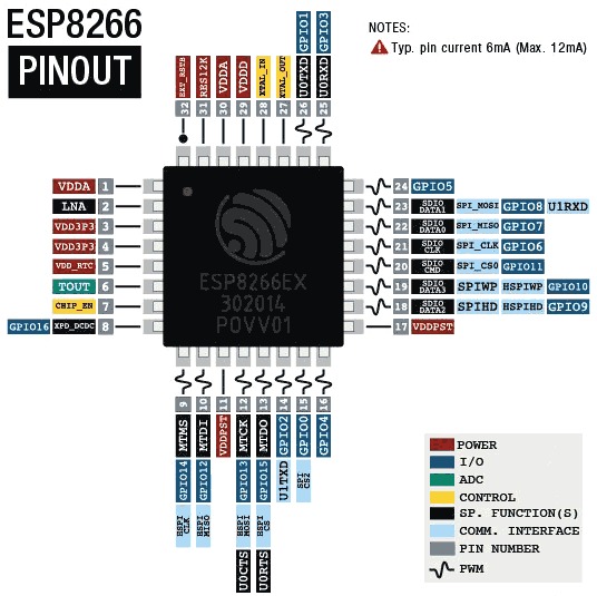
| − | [[File:ESP8266-Pinout.jpeg|left|thumb]] | + | [[File:ESP8266-Pinout.jpeg|left|thumb|link=Special:FilePath/ESP8266-Pinout.jpeg]] |
| − | [[File:ESP8266-Basic-circuit.png|center|thumb]] | + | [[File:ESP8266-Basic-circuit.png|center|thumb|link=Special:FilePath/ESP8266-Basic-circuit.png]] |
<br /> | <br /> | ||
| − | [[File:ESP8266-symbol.png|none|thumb]] | + | [[File:ESP8266-symbol.png|none|thumb|link=Special:FilePath/ESP8266-symbol.png]] |
| + | |||
| + | ==Notes== | ||
| + | |||
| + | *IO13 & IO16 don't seem usable for I2C... (at least under Tasmota...) | ||
| + | |||
| + | ===GPIO Pins=== | ||
| + | {| class="wikitable" | ||
| + | |+ | ||
| + | !GPIO | ||
| + | !RAW | ||
| + | PIN | ||
| + | !Arduino | ||
| + | !Input | ||
| + | !Output | ||
| + | !Boot State | ||
| + | ! | ||
| + | !Notes | ||
| + | !01 | ||
| + | !01F | ||
| + | !M3 | ||
| + | !07 | ||
| + | !12 | ||
| + | !D1 mini | ||
| + | |- | ||
| + | |ADC0 | ||
| + | |6 | ||
| + | |A0 | ||
| + | |'''Analog Input''' | ||
| + | |(not useable) | ||
| + | | | ||
| + | | | ||
| + | | | ||
| + | |X | ||
| + | | | ||
| + | |X | ||
| + | | | ||
| + | | | ||
| + | | | ||
| + | |- | ||
| + | |0 | ||
| + | |15 | ||
| + | |D3 | ||
| + | |pulled up | ||
| + | |(caution) | ||
| + | | | ||
| + | |HSPI_MISO, I2SI_DATA | ||
| + | |connected to FLASH button, boot fails if pulled LOW | ||
| + | | | ||
| + | | | ||
| + | | | ||
| + | | | ||
| + | | | ||
| + | | | ||
| + | |- | ||
| + | |1 | ||
| + | |26 | ||
| + | |TX | ||
| + | |'''TX pin''' | ||
| + | |(caution) | ||
| + | |'''HIGH''' | ||
| + | |UART0_TXD | ||
| + | |debug output at boot, boot fails if pulled LOW | ||
| + | | | ||
| + | | | ||
| + | | | ||
| + | | | ||
| + | | | ||
| + | | | ||
| + | |- | ||
| + | |2 | ||
| + | |14 | ||
| + | |D4 | ||
| + | |pulled up | ||
| + | |(caution) | ||
| + | |'''HIGH?''' | ||
| + | |UART1_TXD | ||
| + | |boot fails if pulled LOW | ||
| + | | | ||
| + | | | ||
| + | |on-board LED | ||
| + | | | ||
| + | |on-board LED | ||
| + | |on-board LED | ||
| + | |- | ||
| + | |3 | ||
| + | |25 | ||
| + | |RX | ||
| + | |(caution) | ||
| + | |'''RX pin''' | ||
| + | |'''HIGH''' | ||
| + | |UART0_RXD | ||
| + | | | ||
| + | | | ||
| + | | | ||
| + | | | ||
| + | | | ||
| + | | | ||
| + | | | ||
| + | |- | ||
| + | |4 | ||
| + | |16 | ||
| + | |D2 | ||
| + | |no pullup | ||
| + | | | ||
| + | | | ||
| + | | | ||
| + | |often used as <code>SDA</code> (I2C) | ||
| + | |X | ||
| + | | | ||
| + | | | ||
| + | | | ||
| + | | | ||
| + | | | ||
| + | |- | ||
| + | |5 | ||
| + | |24 | ||
| + | |D1 | ||
| + | | | ||
| + | | | ||
| + | | | ||
| + | |IR_R | ||
| + | |often used as <code>SCL</code> (I2C) | ||
| + | |X | ||
| + | | | ||
| + | |X | ||
| + | | | ||
| + | | | ||
| + | | | ||
| + | |- | ||
| + | |6 | ||
| + | |21 | ||
| + | | | ||
| + | | | ||
| + | | | ||
| + | | | ||
| + | | | ||
| + | |connected to the flash chip | ||
| + | |X | ||
| + | |X | ||
| + | |X | ||
| + | |X | ||
| + | | | ||
| + | |X | ||
| + | |- | ||
| + | |7 | ||
| + | |22 | ||
| + | | | ||
| + | | | ||
| + | | | ||
| + | | | ||
| + | | | ||
| + | |connected to the flash chip | ||
| + | |X | ||
| + | |X | ||
| + | |X | ||
| + | |X | ||
| + | | | ||
| + | |X | ||
| + | |- | ||
| + | |8 | ||
| + | |23 | ||
| + | | | ||
| + | | | ||
| + | | | ||
| + | | | ||
| + | | | ||
| + | |connected to the flash chip | ||
| + | |X | ||
| + | |X | ||
| + | |X | ||
| + | |X | ||
| + | | | ||
| + | |X | ||
| + | |- | ||
| + | |9 | ||
| + | |18 | ||
| + | |SD2 | ||
| + | | | ||
| + | | | ||
| + | |'''HIGH''' | ||
| + | | | ||
| + | |connected to the flash chip | ||
| + | |X | ||
| + | |X | ||
| + | |X | ||
| + | |X | ||
| + | | | ||
| + | |X | ||
| + | |- | ||
| + | |10 | ||
| + | |19 | ||
| + | |SD3 | ||
| + | | | ||
| + | | | ||
| + | |'''HIGH''' | ||
| + | | | ||
| + | |connected to the flash chip | ||
| + | |X | ||
| + | |X | ||
| + | |X | ||
| + | |X | ||
| + | | | ||
| + | |X | ||
| + | |- | ||
| + | |11 | ||
| + | |20 | ||
| + | | | ||
| + | | | ||
| + | | | ||
| + | | | ||
| + | | | ||
| + | |connected to the flash chip | ||
| + | |X | ||
| + | |X | ||
| + | |X | ||
| + | |X | ||
| + | | | ||
| + | |X | ||
| + | |- | ||
| + | |12 | ||
| + | |10 | ||
| + | |D6 | ||
| + | | | ||
| + | | | ||
| + | | | ||
| + | |HSPI_MISO | ||
| + | |<code>SPI</code> (MISO) | ||
| + | |X | ||
| + | | | ||
| + | |X | ||
| + | | | ||
| + | | | ||
| + | | | ||
| + | |- | ||
| + | |13 | ||
| + | |12 | ||
| + | |D7 | ||
| + | |no pullup | ||
| + | | | ||
| + | | | ||
| + | |HSPI_MOSI, UART0_CTS | ||
| + | |<code>SPI</code> (MOSI) | ||
| + | |X | ||
| + | | | ||
| + | | | ||
| + | | | ||
| + | | | ||
| + | | | ||
| + | |- | ||
| + | |14 | ||
| + | |9 | ||
| + | |D5 | ||
| + | | | ||
| + | | | ||
| + | | | ||
| + | |HSPI_CLK | ||
| + | |<code>SPI</code> (SCLK) | ||
| + | |X | ||
| + | | | ||
| + | | | ||
| + | | | ||
| + | | | ||
| + | | | ||
| + | |- | ||
| + | |15 | ||
| + | |13 | ||
| + | |D8 | ||
| + | |pulled to GND | ||
| + | |(caution) | ||
| + | |'''LOW''' | ||
| + | |MTDO, HSPICS, UART0_RTS | ||
| + | |<code>SPI</code> (CS) | ||
| + | |||
| + | Boot fails if pulled HIGH | ||
| + | |X | ||
| + | | | ||
| + | |X | ||
| + | | | ||
| + | | | ||
| + | | | ||
| + | |- | ||
| + | |16 | ||
| + | |8 | ||
| + | |D0 | ||
| + | |no interrupt | ||
| + | |no PWM or I2C support | ||
| + | |'''HIGH''' | ||
| + | | | ||
| + | |used to wake up from deep sleep | ||
| + | |X | ||
| + | | | ||
| + | | | ||
| + | | | ||
| + | | | ||
| + | | | ||
| + | |} | ||
==Modules== | ==Modules== | ||
*[[ESP-01|ESP-01]] | *[[ESP-01|ESP-01]] | ||
| + | *[[ESP-01F]] | ||
*[[ESP-M3]] | *[[ESP-M3]] | ||
*[[ESP-07|ESP-07]] | *[[ESP-07|ESP-07]] | ||
*[[ESP-12|ESP-12]] | *[[ESP-12|ESP-12]] | ||
| − | |||
*[[LOLIN D1 mini]] | *[[LOLIN D1 mini]] | ||
===[[IoT - Sonoff|Sonoff]]=== | ===[[IoT - Sonoff|Sonoff]]=== | ||
| − | Most (all?) of these are basically ESP8266 or | + | Most (all?) of these are basically ESP8266 or ESP8285 controlled relays |
==Firmware== | ==Firmware== | ||
| Line 79: | Line 375: | ||
File:UMH3N Internals.png | File:UMH3N Internals.png | ||
File:ESP01 Programmed without button pressing.jpg | File:ESP01 Programmed without button pressing.jpg | ||
| − | </gallery>< | + | </gallery> |
| + | |||
| + | ==Booting The ESP82xx== | ||
| + | {| class="wikitable" | ||
| + | |- | ||
| + | !Mode!!CH_PD (EN)!!RST!!GPIO15!!GPIO0!!GPIO2!!TXD0 | ||
| + | |- | ||
| + | |'''Download'''||high||high||low||low||high||high | ||
| + | |- | ||
| + | |'''Run'''||high||high||low||high||high||high | ||
| + | |} | ||
| + | |||
| + | ==Communicating with the ESP8266== | ||
| + | ===Physical Connection=== | ||
| + | |||
| + | Choose your favourite USB-Serial UART. (I like the [https://www.banggood.com/CJMCU-340-CH340G-TTL-To-USB-STC-Downloader-Serial-Communication-Module-Pin-All-Leads-p-1149176.html CJMCU-340]) | ||
| + | |||
| + | '''NOTE:''' The ESP8266 is a 3.3V device. Don't use a 5V UART! | ||
| + | |||
| + | GPIO1 = TxD | ||
| + | |||
| + | GPIO3 = RxD | ||
| + | |||
| + | As always, Connect TxD to RX-in on your UART & RxD to TX-out on your UART. | ||
| + | |||
| + | ===Talking to it=== | ||
| + | |||
| + | '''NOTE:''' The ESP initially spits out debug information at 74880 baud. This is not a standard speed. ([http://cholla.mmto.org/esp8266/weird_baud/ some discussion about this]) | ||
| + | |||
| + | Choose your favourite terminal program & point it at the appropriate port. | ||
| + | |||
| + | In this example, I'll use miniterm (Because it's simple) | ||
| + | |||
| + | *<code>miniterm.py /dev/ttyUSB0 74880</code> | ||
| + | |||
| + | Gives me this (with an ESP-M3 that's been flashed & made ready for use...): | ||
| + | |||
| + | --- Miniterm on /dev/ttyUSB0 74880,8,N,1 --- | ||
| + | --- Quit: Ctrl+] | Menu: Ctrl+T | Help: Ctrl+T followed by Ctrl+H --- | ||
| + | |||
| + | ets Jan 8 2013,rst cause:1, boot mode:(3,6) | ||
| + | |||
| + | load 0x4010f000, len 3584, room 16 | ||
| + | tail 0 | ||
| + | chksum 0xb0 | ||
| + | csum 0xb0 | ||
| + | v2843a5ac | ||
| + | ~ld | ||
| + | ␄␝␑␑␁" ��^�K␕���)␄5␑�␌7mX'\��o␇�␄5%�iHD��U␁'Rܥ@␁␒␕␝�␇!␕�␑t␅!o�Y��␓C����+��J[�`�␙��P␂� | ||
| + | |||
| + | See all that weirdness on the last few lines? That's data at a different speed. The device has booted & is trying to talk to us... | ||
| + | |||
| + | Starting over with: | ||
| + | |||
| + | *<code>miniterm.py /dev/ttyUSB0 115200</code> | ||
| + | |||
| + | Gives me this: | ||
| + | |||
| + | --- Miniterm on /dev/ttyUSB0 115200,8,N,1 --- | ||
| + | --- Quit: Ctrl+] | Menu: Ctrl+T | Help: Ctrl+T followed by Ctrl+H --- | ||
| + | rd␀$��|␀�l�|␃␌␌␄�␄l�␄c|��␃�␒�;�cl␄c��g'�log���␌c␜8��lrl;lx�o�␘␃␌␄�␌d␌��␌␄␌#␄g�| | ||
| + | ␃�$�␄�#��no�␀$��l ␃�␛␓og␄l`␃␏␂'{���g␄␌c␃l`␃␇s��n␌␄c␂d`␂�c␌␄�␜␂�l{� ␃��o�␃ | ||
| + | 00:00:00 CFG: Loaded from flash at F9, Count 89 | ||
| + | 00:00:00 QPC: Count 2 | ||
| + | 00:00:00 Project tasmota ESP-M3-Everything-1 Version 8.5.0(tasmota)-2_7_4_1 | ||
| + | |||
| + | Oh... Look. It's a Tasmota device. | ||
| + | |||
| + | Notice the weirdness between the banner & the first line with 00:00:00 at the start? That's the debug information coming in at 74880 that we saw in the previous example. | ||
| + | |||
| + | ===Interpreting the Debug Information=== | ||
| + | Here's the output from an ESP-07 that hasn't been flashed yet (IOW... Factory fresh): | ||
| + | --- Miniterm on /dev/ttyUSB0 74880,8,N,1 --- | ||
| + | --- Quit: Ctrl+] | Menu: Ctrl+T | Help: Ctrl+T followed by Ctrl+H --- | ||
| + | |||
| + | ets Jan 8 2013,rst cause:2, boot mode:(3,7) | ||
| + | |||
| + | load 0x40100000, len 27728, room 16 | ||
| + | tail 0 | ||
| + | chksum 0x2a | ||
| + | load 0x3ffe8000, len 2124, room 8 | ||
| + | tail 4 | ||
| + | chksum 0x07 | ||
| + | load 0x3ffe8850, len 9276, room 4 | ||
| + | tail 8 | ||
| + | chksum 0xba | ||
| + | csum 0xba | ||
| + | rf[112] : 00 | ||
| + | rf[113] : 00 | ||
| + | rf[114] : 01 | ||
| + | |||
| + | SDK ver: 1.5.4(baaeaebb) compiled @ May 17 2016 19:23:54 | ||
| + | phy ver: 972, pp ver: 10.1 | ||
| + | |||
| + | )�L� | ||
| + | |||
| + | & the same device booted into flashing mode: | ||
| + | |||
| + | --- Miniterm on /dev/ttyUSB0 74880,8,N,1 --- | ||
| + | --- Quit: Ctrl+] | Menu: Ctrl+T | Help: Ctrl+T followed by Ctrl+H --- | ||
| + | |||
| + | ets Jan 8 2013,rst cause:2, boot mode:(1,7) | ||
| + | |||
| + | [[ESP8266 - interpreting the Debug Information when things go wrong|Notes on interpreting the Debug Information when things go wrong]] | ||
| + | |||
==Information Links== | ==Information Links== | ||
| − | [[File:Esp8266ex datasheet.pdf|thumb|right|200px|ESP8266 Datasheet]] [[File:ESP8266 ESP32.pdf|thumb|right|200px|Kolban’s book on the ESP8266]] | + | [[File:Esp8266ex datasheet.pdf|thumb|right|200px|ESP8266 Datasheet|link=Special:FilePath/Esp8266ex_datasheet.pdf]] [[File:Esp8266 hardware design guidelines en.pdf|thumb|right|200px|Esp8266 Hardware Design Guidelines|link=Special:FilePath/Esp8266_hardware_design_guidelines_en.pdf]] [[File:Esp8266-technical reference en.pdf|thumb|right|200px|ESP8266 Technical Reference|link=Special:FilePath/Esp8266-technical_reference_en.pdf]] [[File:ESP8266 ESP32.pdf|thumb|right|200px|Kolban’s book on the ESP8266|link=Special:FilePath/ESP8266_ESP32.pdf]] |
*<span style="font-size:x-large">'''[https://tttapa.github.io/ESP8266/Chap01%20-%20ESP8266.html A Beginner's Guide to the ESP8266]'''</span> | *<span style="font-size:x-large">'''[https://tttapa.github.io/ESP8266/Chap01%20-%20ESP8266.html A Beginner's Guide to the ESP8266]'''</span> | ||
| Line 99: | Line 499: | ||
*[http://neilkolban.com/tech/esp8266/ Kolban’s book on the ESP8266] | *[http://neilkolban.com/tech/esp8266/ Kolban’s book on the ESP8266] | ||
*[http://henrysbench.capnfatz.com/henrys-bench/arduino-projects-tips-and-more/esp8266ex-pinouts-and-connections/ ESP8266EX Pinouts and Connections] | *[http://henrysbench.capnfatz.com/henrys-bench/arduino-projects-tips-and-more/esp8266ex-pinouts-and-connections/ ESP8266EX Pinouts and Connections] | ||
| + | *[https://randomnerdtutorials.com/esp8266-pinout-reference-gpios/ ESP8266 Pinout Reference: Which GPIO pins should you use?] | ||
| + | *[https://rabbithole.wwwdotorg.org/2017/03/28/esp8266-gpio.html ESP8266 GPIO Behaviour at Boot] | ||
==Usage Links== | ==Usage Links== | ||
| Line 130: | Line 532: | ||
*[http://www.instructables.com/id/Making-Soldering-an-ESP-07-Breakout-Board/ Making & Soldering an ESP-07 Breakout Board] | *[http://www.instructables.com/id/Making-Soldering-an-ESP-07-Breakout-Board/ Making & Soldering an ESP-07 Breakout Board] | ||
| + | **Or... [[IoT_-_ESP-07_Everything!|Even better]] (IMO) | ||
*'''''[http://www.esp8266-projects.com/2015/03/mailbag-arrival-new-battery-solution.html New Battery solution for ESP8266 Modules]''''' | *'''''[http://www.esp8266-projects.com/2015/03/mailbag-arrival-new-battery-solution.html New Battery solution for ESP8266 Modules]''''' | ||
| Line 146: | Line 549: | ||
==Projects== | ==Projects== | ||
| + | *[https://hackaday.io/page/1304-virtual-serial-port-tunnel-to-use-with-esp-link Virtual serial port tunnel (to use with ESP-Link)] | ||
| + | **Possibly useful for connecting serial devices over WiFi | ||
| + | **[https://github.com/jeelabs/esp-link ESP-Link] | ||
*[http://www.instructables.com/id/WiFi-Plant-Watering-ESP8266/ WiFi Plant Watering ESP8266] | *[http://www.instructables.com/id/WiFi-Plant-Watering-ESP8266/ WiFi Plant Watering ESP8266] | ||
*[http://www.instructables.com/id/WIFI-Battery-Monitor-System-ESP8266/ WIFI Battery Monitor System - ESP8266] | *[http://www.instructables.com/id/WIFI-Battery-Monitor-System-ESP8266/ WIFI Battery Monitor System - ESP8266] | ||
| Line 182: | Line 588: | ||
*[https://openhomeautomation.net/esp8266-battery/ How to Run Your ESP8266 for Years on a Battery] | *[https://openhomeautomation.net/esp8266-battery/ How to Run Your ESP8266 for Years on a Battery] | ||
*[https://www.youtube.com/watch?v=TVXaRl90Seg New ESP Mini-Project (Web Config!!!) & Announcement] | *[https://www.youtube.com/watch?v=TVXaRl90Seg New ESP Mini-Project (Web Config!!!) & Announcement] | ||
| + | |||
| + | ===Some Interesting Observations About Parts On Hand=== | ||
| + | |||
| + | {| class="wikitable" | ||
| + | |- | ||
| + | |<br /> | ||
| + | |ESP-01 | ||
| + | |ESP-M3 (unmarked) | ||
| + | |ESP-M3 (marked) | ||
| + | |ESP-07 | ||
| + | |ESP-12 | ||
| + | |D1-Mini | ||
| + | |ESP32 | ||
| + | |- | ||
| + | ! colspan="8" |ESP Chip | ||
| + | |- | ||
| + | !Chip Type | ||
| + | |ESP8266 | ||
| + | |ESP8266 | ||
| + | |ESP8266 | ||
| + | |ESP8266 | ||
| + | |ESP8266 | ||
| + | |ESP8266 | ||
| + | |ESP32 | ||
| + | |- | ||
| + | !Chip | ||
| + | |ESP8266EX | ||
| + | |ESP8285 | ||
| + | |ESP8285 | ||
| + | |ESP8266EX | ||
| + | |ESP8266EX | ||
| + | |ESP8266EX | ||
| + | |ESP32-D0WDQ6 (revision 1) | ||
| + | |- | ||
| + | !Chip ID | ||
| + | |0x00039be7 | ||
| + | |0x0072797d | ||
| + | |0x0070c38d | ||
| + | |0x0075ad0d | ||
| + | |0x00237e85 | ||
| + | |0x00650f82 | ||
| + | |ESP32 has no Chip ID. Reading MAC instead. | ||
| + | |- | ||
| + | !Features | ||
| + | |WiFi | ||
| + | |WiFi, Embedded Flash | ||
| + | |WiFi, Embedded Flash | ||
| + | |WiFi | ||
| + | |WiFi | ||
| + | |WiFi | ||
| + | |WiFi, BT, Dual Core, 240MHz, VRef calibration in efuse, Coding Scheme None | ||
| + | |- | ||
| + | !Crystal | ||
| + | |26MHz | ||
| + | |26MHz | ||
| + | |26MHz | ||
| + | |26MHz | ||
| + | |26MHz | ||
| + | |26MHz | ||
| + | |40MHz | ||
| + | |- | ||
| + | !MAC | ||
| + | |4c:11:ae:03:9b:e7 | ||
| + | |84:0d:8e:72:79:7d | ||
| + | |c8:2b:96:70:c3:8d | ||
| + | |50:02:91:75:ad:0d | ||
| + | |40:f5:20:23:7e:85 | ||
| + | |2c:f4:32:65:0f:82 | ||
| + | |cc:50:e3:b5:df:c8 | ||
| + | |- | ||
| + | ! colspan="8" |Flash Chip | ||
| + | |- | ||
| + | !Manufacturer | ||
| + | |5e | ||
| + | |51 | ||
| + | |a1 | ||
| + | |d8 | ||
| + | |20 | ||
| + | |5e | ||
| + | |20 | ||
| + | |- | ||
| + | !Device | ||
| + | |4014 | ||
| + | |4014 | ||
| + | |4015 | ||
| + | |4014 | ||
| + | |4016 | ||
| + | |4016 | ||
| + | |4016 | ||
| + | |- | ||
| + | !Detected flash size | ||
| + | |1MB | ||
| + | |1MB | ||
| + | |2MB | ||
| + | |1MB | ||
| + | |4MB | ||
| + | |4MB | ||
| + | |4MB | ||
| + | |} | ||
Latest revision as of 00:42, 24 February 2022


Contents
Notes
- IO13 & IO16 don't seem usable for I2C... (at least under Tasmota...)
GPIO Pins
| GPIO | RAW
PIN |
Arduino | Input | Output | Boot State | Notes | 01 | 01F | M3 | 07 | 12 | D1 mini | |
|---|---|---|---|---|---|---|---|---|---|---|---|---|---|
| ADC0 | 6 | A0 | Analog Input | (not useable) | X | X | |||||||
| 0 | 15 | D3 | pulled up | (caution) | HSPI_MISO, I2SI_DATA | connected to FLASH button, boot fails if pulled LOW | |||||||
| 1 | 26 | TX | TX pin | (caution) | HIGH | UART0_TXD | debug output at boot, boot fails if pulled LOW | ||||||
| 2 | 14 | D4 | pulled up | (caution) | HIGH? | UART1_TXD | boot fails if pulled LOW | on-board LED | on-board LED | on-board LED | |||
| 3 | 25 | RX | (caution) | RX pin | HIGH | UART0_RXD | |||||||
| 4 | 16 | D2 | no pullup | often used as SDA (I2C)
|
X | ||||||||
| 5 | 24 | D1 | IR_R | often used as SCL (I2C)
|
X | X | |||||||
| 6 | 21 | connected to the flash chip | X | X | X | X | X | ||||||
| 7 | 22 | connected to the flash chip | X | X | X | X | X | ||||||
| 8 | 23 | connected to the flash chip | X | X | X | X | X | ||||||
| 9 | 18 | SD2 | HIGH | connected to the flash chip | X | X | X | X | X | ||||
| 10 | 19 | SD3 | HIGH | connected to the flash chip | X | X | X | X | X | ||||
| 11 | 20 | connected to the flash chip | X | X | X | X | X | ||||||
| 12 | 10 | D6 | HSPI_MISO | SPI (MISO)
|
X | X | |||||||
| 13 | 12 | D7 | no pullup | HSPI_MOSI, UART0_CTS | SPI (MOSI)
|
X | |||||||
| 14 | 9 | D5 | HSPI_CLK | SPI (SCLK)
|
X | ||||||||
| 15 | 13 | D8 | pulled to GND | (caution) | LOW | MTDO, HSPICS, UART0_RTS | SPI (CS)
Boot fails if pulled HIGH |
X | X | ||||
| 16 | 8 | D0 | no interrupt | no PWM or I2C support | HIGH | used to wake up from deep sleep | X |
Modules
Sonoff
Most (all?) of these are basically ESP8266 or ESP8285 controlled relays
Firmware
ESP8266 WiFi Connection manager
Original?
Tasmota
Espruino
ESPurna
ESP-MQTT
ESP-go
NodeMcu
ESP Easy
ESPHelper
WLED
- Home
- Many bugs seem to appear with version changes...
- 0.8.6 seems functional on my D1 Minis. (Tho it self-reports as 0.8.4)
- Many bugs seem to appear with version changes...
Setting up Modules


Booting The ESP82xx
| Mode | CH_PD (EN) | RST | GPIO15 | GPIO0 | GPIO2 | TXD0 |
|---|---|---|---|---|---|---|
| Download | high | high | low | low | high | high |
| Run | high | high | low | high | high | high |
Communicating with the ESP8266
Physical Connection
Choose your favourite USB-Serial UART. (I like the CJMCU-340)
NOTE: The ESP8266 is a 3.3V device. Don't use a 5V UART!
GPIO1 = TxD
GPIO3 = RxD
As always, Connect TxD to RX-in on your UART & RxD to TX-out on your UART.
Talking to it
NOTE: The ESP initially spits out debug information at 74880 baud. This is not a standard speed. (some discussion about this)
Choose your favourite terminal program & point it at the appropriate port.
In this example, I'll use miniterm (Because it's simple)
miniterm.py /dev/ttyUSB0 74880
Gives me this (with an ESP-M3 that's been flashed & made ready for use...):
--- Miniterm on /dev/ttyUSB0  74880,8,N,1 ---
--- Quit: Ctrl+] | Menu: Ctrl+T | Help: Ctrl+T followed by Ctrl+H ---

 ets Jan  8 2013,rst cause:1, boot mode:(3,6)

load 0x4010f000, len 3584, room 16
tail 0
chksum 0xb0
csum 0xb0
v2843a5ac
~ld
␄␝␑␑␁"	��^�K␕���)␄5␑�␌7mX'\��o␇�␄5%�iHD��U␁'Rܥ@␁␒␕␝�␇!␕�␑t␅!o�Y��␓C����+��J[�`�␙��P␂�
See all that weirdness on the last few lines? That's data at a different speed. The device has booted & is trying to talk to us...
Starting over with:
miniterm.py /dev/ttyUSB0 115200
Gives me this:
--- Miniterm on /dev/ttyUSB0  115200,8,N,1 ---
--- Quit: Ctrl+] | Menu: Ctrl+T | Help: Ctrl+T followed by Ctrl+H ---
rd␀$��|␀�l�|␃␌␌␄�␄l�␄c|��␃�␒�;�cl␄c��g'�log���␌c␜8��lrl;lx�o�␘␃␌␄�␌d␌��␌␄␌#␄g�|
␃�$�␄�#��no�␀$��l ␃�␛␓og␄l`␃␏␂'{���g␄␌c␃l`␃␇s��n␌␄c␂d`␂�c␌␄�␜␂�l{� ␃��o�␃
00:00:00 CFG: Loaded from flash at F9, Count 89
00:00:00 QPC: Count 2
00:00:00 Project tasmota ESP-M3-Everything-1 Version 8.5.0(tasmota)-2_7_4_1
Oh... Look. It's a Tasmota device.
Notice the weirdness between the banner & the first line with 00:00:00 at the start? That's the debug information coming in at 74880 that we saw in the previous example.
Interpreting the Debug Information
Here's the output from an ESP-07 that hasn't been flashed yet (IOW... Factory fresh):
--- Miniterm on /dev/ttyUSB0  74880,8,N,1 ---
--- Quit: Ctrl+] | Menu: Ctrl+T | Help: Ctrl+T followed by Ctrl+H ---

 ets Jan  8 2013,rst cause:2, boot mode:(3,7)

load 0x40100000, len 27728, room 16
tail 0
chksum 0x2a
load 0x3ffe8000, len 2124, room 8
tail 4
chksum 0x07
load 0x3ffe8850, len 9276, room 4
tail 8
chksum 0xba
csum 0xba
rf[112] : 00
rf[113] : 00
rf[114] : 01

SDK ver: 1.5.4(baaeaebb) compiled @ May 17 2016 19:23:54
phy ver: 972, pp ver: 10.1

)�L�
& the same device booted into flashing mode:
--- Miniterm on /dev/ttyUSB0  74880,8,N,1 ---
--- Quit: Ctrl+] | Menu: Ctrl+T | Help: Ctrl+T followed by Ctrl+H ---

 ets Jan  8 2013,rst cause:2, boot mode:(1,7)
Notes on interpreting the Debug Information when things go wrong
Information Links

- A Beginner's Guide to the ESP8266
- Espressif Systems (manufacturer)
- ESP8266 Module Family
- Different types of ESP8266 module
- On Wikipedia
- ESP8266 Serial WIFI Module (ITEAD Wiki)
- Official Forum
- ESP8266 Community Forum
- Espruino Software Reference
- Kolban’s book on the ESP8266
- ESP8266EX Pinouts and Connections
- ESP8266 Pinout Reference: Which GPIO pins should you use?
- ESP8266 GPIO Behaviour at Boot
Usage Links
- ESP8266 WiFi Module for Dummies
- ESP8266 Serial Interface to WiFi
- Simple Arduino Web Server on ESP-07/ESP-12 Tutorial
- Cheap and Easy WiFi (IoT) Tutorial Part 1 - ESP8266 Setup/Intro
- Cheap and Easy WiFi (IoT) Tutorial Part 2 - ESP8266 Arduino Code
- ESP8266 Native
- Control ESP8266 over the internet (from anywhere)
- Esp8266 firmware update
- WiFi / Internet Controlled Relays using ESP8266 - Quick, 30 minutes IoT project
- Telnet server example
Programming
- How to wire an ESP07/12 for programming
- The Simple Guide to Flashing Your ESP8266 Firmware
- Upload sketch to the ESP8266 (ESP-07/ESP-12) using Arduino IDE
- ESP8266 as Arduino
- Update the Firmware in Your ESP8266 Wi-Fi Module
- ESP8266 core for Arduino
Hardware
- Making & Soldering an ESP-07 Breakout Board
- Or... Even better (IMO)
- New Battery solution for ESP8266 Modules
Ethernet
- ENC28J60 - ETHERNET CABLE CONNECTION TO ESP8266 (ESPHTTPD)
- Ethernet Controller Discovered in the ESP8266
- Wired Networking For The ESP8266
& More
- ESP8266 Power Saving
Projects
- Virtual serial port tunnel (to use with ESP-Link)
- Possibly useful for connecting serial devices over WiFi
- ESP-Link
- WiFi Plant Watering ESP8266
- WIFI Battery Monitor System - ESP8266
- Using an esp8266 arduino to control a relay using home-assistant
- ESP8266 Wireless Toilet Usage Indicator (Smart Home)
- Free Dynamic DNS Server with Esp8266 and OSD FOSCAM Webcam Interface
- ESP8266 Automatic Router Restart
- ESP8266 BASIC IoT Light
- MASLOW: an Open WiFi Detector with ESP8266
- ESP8266 - $5 internet connected switch
- Wifi Relay With ESP8266
- ESP8266 Internet Alarm
- ESP8266 Wifi Timer Switch for AC Loads
- Wifi enabled 8×64 pixel LED matrix display
- ESP8266 GMail sender
- Very Cheap/Simple WiFi Shield for Arduino and microprocessors
- ESP8266 Weather Widget
- ESP8266 - $5 internet connected switch
- Wifi Dot Matrix Sign
- ESP Weather Forecaster
- Clear Sky Indicator for Astronomy! (Another ESP Weather Forcaster)
- Kevin Darrahs take on the idea...
- Some bunos ideas to look into, like EEPROM wear leveling
Random
Bits & Pieces
- Display Temperature and Humidity and upload to ThingSpeak
- How to Run Your ESP8266 for Years on a Battery
- New ESP Mini-Project (Web Config!!!) & Announcement
Some Interesting Observations About Parts On Hand
| ESP-01 | ESP-M3 (unmarked) | ESP-M3 (marked) | ESP-07 | ESP-12 | D1-Mini | ESP32 | |
| ESP Chip | |||||||
|---|---|---|---|---|---|---|---|
| Chip Type | ESP8266 | ESP8266 | ESP8266 | ESP8266 | ESP8266 | ESP8266 | ESP32 |
| Chip | ESP8266EX | ESP8285 | ESP8285 | ESP8266EX | ESP8266EX | ESP8266EX | ESP32-D0WDQ6 (revision 1) |
| Chip ID | 0x00039be7 | 0x0072797d | 0x0070c38d | 0x0075ad0d | 0x00237e85 | 0x00650f82 | ESP32 has no Chip ID. Reading MAC instead. |
| Features | WiFi | WiFi, Embedded Flash | WiFi, Embedded Flash | WiFi | WiFi | WiFi | WiFi, BT, Dual Core, 240MHz, VRef calibration in efuse, Coding Scheme None |
| Crystal | 26MHz | 26MHz | 26MHz | 26MHz | 26MHz | 26MHz | 40MHz |
| MAC | 4c:11:ae:03:9b:e7 | 84:0d:8e:72:79:7d | c8:2b:96:70:c3:8d | 50:02:91:75:ad:0d | 40:f5:20:23:7e:85 | 2c:f4:32:65:0f:82 | cc:50:e3:b5:df:c8 |
| Flash Chip | |||||||
| Manufacturer | 5e | 51 | a1 | d8 | 20 | 5e | 20 |
| Device | 4014 | 4014 | 4015 | 4014 | 4016 | 4016 | 4016 |
| Detected flash size | 1MB | 1MB | 2MB | 1MB | 4MB | 4MB | 4MB |