ESP8266 / ESP8285
Contents
Notes
- IO13 & IO16 don't seem usable for I2C... (at least under Tasmota...)
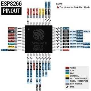
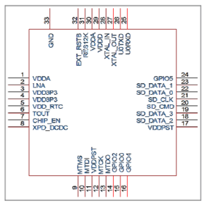
GPIO Pins
| GPIO | Input | Output | Boot State | Notes | 01 | 01F | M3 | 07 | 12 | D1 mini | |
|---|---|---|---|---|---|---|---|---|---|---|---|
| ADC0 | Analog Input | (not useable) | X | X | |||||||
| 0 | pulled up | (caution) | HSPI_MISO, I2SI_DATA | connected to FLASH button, boot fails if pulled LOW | |||||||
| 1 | TX pin | (caution) | HIGH | UART0_TXD | debug output at boot, boot fails if pulled LOW | ||||||
| 2 | pulled up | (caution) | HIGH? | UART1_TXD | boot fails if pulled LOW | on-board LED | on-board LED | on-board LED | |||
| 3 | (caution) | RX pin | HIGH | UART0_RXD | |||||||
| 4 | often used as SDA (I2C)
|
X | |||||||||
| 5 | IR_R | often used as SCL (I2C)
|
X | X | |||||||
| 6 | connected to the flash chip | X | X | X | X | X | |||||
| 7 | connected to the flash chip | X | X | X | X | X | |||||
| 8 | connected to the flash chip | X | X | X | X | X | |||||
| 9 | HIGH | connected to the flash chip | X | X | X | X | X | ||||
| 10 | HIGH | connected to the flash chip | X | X | X | X | X | ||||
| 11 | connected to the flash chip | X | X | X | X | X | |||||
| 12 | HSPI_MISO | SPI (MISO)
|
X | X | |||||||
| 13 | HSPI_MOSI, UART0_CTS | SPI (MOSI)
|
X | ||||||||
| 14 | HSPI_CLK | SPI (SCLK)
|
X | ||||||||
| 15 | pulled to GND | (caution) | LOW | MTDO, HSPICS, UART0_RTS | SPI (CS)
Boot fails if pulled HIGH |
X | X | ||||
| 16 | no interrupt | no PWM or I2C support | HIGH | used to wake up from deep sleep | X |
Modules
Sonoff
Most (all?) of these are basically ESP8266 or ESP8285 controlled relays
Firmware
ESP8266 WiFi Connection manager
Original?
Tasmota
Espruino
ESPurna
ESP-MQTT
ESP-go
NodeMcu
ESP Easy
ESPHelper
WLED
- Home
- Many bugs seem to appear with version changes...
- 0.8.6 seems functional on my D1 Minis. (Tho it self-reports as 0.8.4)
- Many bugs seem to appear with version changes...
Setting up Modules
Booting The ESP82xx
| Mode | CH_PD (EN) | RST | GPIO15 | GPIO0 | GPIO2 | TXD0 |
|---|---|---|---|---|---|---|
| Download | high | high | low | low | high | high |
| Run | high | high | low | high | high | high |
Communicating with the ESP8266
Physical Connection
Choose your favourite USB-Serial UART. (I like the CJMCU-340)
NOTE: The ESP8266 is a 3.3V device. Don't use a 5V UART!
GPIO1 = TxD
GPIO3 = RxD
As always, Connect TxD to RX-in on your UART & RxD to TX-out on your UART.
Talking to it
NOTE: The ESP initially spits out debug information at 74880 baud. This is not a standard speed. (some discussion about this)
Choose your favourite terminal program & point it at the appropriate port.
In this example, I'll use miniterm (Because it's simple)
miniterm.py /dev/ttyUSB0 74880
Gives me this (with an ESP-M3 that's been flashed & made ready for use...):
--- Miniterm on /dev/ttyUSB0  74880,8,N,1 ---
--- Quit: Ctrl+] | Menu: Ctrl+T | Help: Ctrl+T followed by Ctrl+H ---

 ets Jan  8 2013,rst cause:1, boot mode:(3,6)

load 0x4010f000, len 3584, room 16
tail 0
chksum 0xb0
csum 0xb0
v2843a5ac
~ld
␄␝␑␑␁"	��^�K␕���)␄5␑�␌7mX'\��o␇�␄5%�iHD��U␁'Rܥ@␁␒␕␝�␇!␕�␑t␅!o�Y��␓C����+��J[�`�␙��P␂�
See all that weirdness on the last few lines? That's data at a different speed. The device has booted & is trying to talk to us...
Starting over with:
miniterm.py /dev/ttyUSB0 115200
Gives me this:
--- Miniterm on /dev/ttyUSB0  115200,8,N,1 ---
--- Quit: Ctrl+] | Menu: Ctrl+T | Help: Ctrl+T followed by Ctrl+H ---
rd␀$��|␀�l�|␃␌␌␄�␄l�␄c|��␃�␒�;�cl␄c��g'�log���␌c␜8��lrl;lx�o�␘␃␌␄�␌d␌��␌␄␌#␄g�|
␃�$�␄�#��no�␀$��l ␃�␛␓og␄l`␃␏␂'{���g␄␌c␃l`␃␇s��n␌␄c␂d`␂�c␌␄�␜␂�l{� ␃��o�␃
00:00:00 CFG: Loaded from flash at F9, Count 89
00:00:00 QPC: Count 2
00:00:00 Project tasmota ESP-M3-Everything-1 Version 8.5.0(tasmota)-2_7_4_1
Oh... Look. It's a Tasmota device.
Notice the weirdness between the banner & the first line with 00:00:00 at the start? That's the debug information coming in at 74880 that we saw in the previous example.
Interpreting the Debug Information
Here's the output from an ESP-07 that hasn't been flashed yet (IOW... Factory fresh):
--- Miniterm on /dev/ttyUSB0  74880,8,N,1 ---
--- Quit: Ctrl+] | Menu: Ctrl+T | Help: Ctrl+T followed by Ctrl+H ---

 ets Jan  8 2013,rst cause:2, boot mode:(3,7)

load 0x40100000, len 27728, room 16
tail 0
chksum 0x2a
load 0x3ffe8000, len 2124, room 8
tail 4
chksum 0x07
load 0x3ffe8850, len 9276, room 4
tail 8
chksum 0xba
csum 0xba
rf[112] : 00
rf[113] : 00
rf[114] : 01

SDK ver: 1.5.4(baaeaebb) compiled @ May 17 2016 19:23:54
phy ver: 972, pp ver: 10.1

)�L�
& the same device booted into flashing mode:
--- Miniterm on /dev/ttyUSB0  74880,8,N,1 ---
--- Quit: Ctrl+] | Menu: Ctrl+T | Help: Ctrl+T followed by Ctrl+H ---

 ets Jan  8 2013,rst cause:2, boot mode:(1,7)
Notes on interpreting the Debug Information when things go wrong
Information Links
- A Beginner's Guide to the ESP8266
- Espressif Systems (manufacturer)
- ESP8266 Module Family
- Different types of ESP8266 module
- On Wikipedia
- ESP8266 Serial WIFI Module (ITEAD Wiki)
- Official Forum
- ESP8266 Community Forum
- Espruino Software Reference
- Kolban’s book on the ESP8266
- ESP8266EX Pinouts and Connections
- ESP8266 Pinout Reference: Which GPIO pins should you use?
- ESP8266 GPIO Behaviour at Boot
Usage Links
- ESP8266 WiFi Module for Dummies
- ESP8266 Serial Interface to WiFi
- Simple Arduino Web Server on ESP-07/ESP-12 Tutorial
- Cheap and Easy WiFi (IoT) Tutorial Part 1 - ESP8266 Setup/Intro
- Cheap and Easy WiFi (IoT) Tutorial Part 2 - ESP8266 Arduino Code
- ESP8266 Native
- Control ESP8266 over the internet (from anywhere)
- Esp8266 firmware update
- WiFi / Internet Controlled Relays using ESP8266 - Quick, 30 minutes IoT project
- Telnet server example
Programming
- How to wire an ESP07/12 for programming
- The Simple Guide to Flashing Your ESP8266 Firmware
- Upload sketch to the ESP8266 (ESP-07/ESP-12) using Arduino IDE
- ESP8266 as Arduino
- Update the Firmware in Your ESP8266 Wi-Fi Module
- ESP8266 core for Arduino
Hardware
- Making & Soldering an ESP-07 Breakout Board
- Or... Even better (IMO)
- New Battery solution for ESP8266 Modules
Ethernet
- ENC28J60 - ETHERNET CABLE CONNECTION TO ESP8266 (ESPHTTPD)
- Ethernet Controller Discovered in the ESP8266
- Wired Networking For The ESP8266
& More
- ESP8266 Power Saving
Projects
- Virtual serial port tunnel (to use with ESP-Link)
- Possibly useful for connecting serial devices over WiFi
- ESP-Link
- WiFi Plant Watering ESP8266
- WIFI Battery Monitor System - ESP8266
- Using an esp8266 arduino to control a relay using home-assistant
- ESP8266 Wireless Toilet Usage Indicator (Smart Home)
- Free Dynamic DNS Server with Esp8266 and OSD FOSCAM Webcam Interface
- ESP8266 Automatic Router Restart
- ESP8266 BASIC IoT Light
- MASLOW: an Open WiFi Detector with ESP8266
- ESP8266 - $5 internet connected switch
- Wifi Relay With ESP8266
- ESP8266 Internet Alarm
- ESP8266 Wifi Timer Switch for AC Loads
- Wifi enabled 8×64 pixel LED matrix display
- ESP8266 GMail sender
- Very Cheap/Simple WiFi Shield for Arduino and microprocessors
- ESP8266 Weather Widget
- ESP8266 - $5 internet connected switch
- Wifi Dot Matrix Sign
- ESP Weather Forecaster
- Clear Sky Indicator for Astronomy! (Another ESP Weather Forcaster)
- Kevin Darrahs take on the idea...
- Some bunos ideas to look into, like EEPROM wear leveling
