Difference between revisions of "IoT - ESP-M3 Everything!"
| (17 intermediate revisions by 2 users not shown) | |||
| Line 1: | Line 1: | ||
| − | + | == '''OOPS!: The symbol & footprint currently in use has an error. The M3 does not break out GPIO13... It breaks out GPIO12. (One of these days, I'll get around to correcting that. For now, GPIO13 is actually GPIO12... :( )''' == | |
| − | [[File:ESP-M3 Everything.png|none|thumb]] | + | [[File:ESP-M3 Everything.png|none|thumb|alt=|This is the one that started it all...]] |
| + | |||
| + | This board carries the [[ESP-M3]] module. | ||
[[:File:ESP-M3 Everything (KiCAD).tar.gz|The KiCAD files]] | [[:File:ESP-M3 Everything (KiCAD).tar.gz|The KiCAD files]] | ||
| Line 6: | Line 8: | ||
[[:File:Esp-M3 Everything (gerbers).zip|The Gerbers]] (Yup... you can get your own boards pretty quick & cheap) | [[:File:Esp-M3 Everything (gerbers).zip|The Gerbers]] (Yup... you can get your own boards pretty quick & cheap) | ||
| − | + | NOTE: If using PCBWAY for production, the size for these boards needs to be input as 61mm x 36.6. If you use a slightly different (slightly rounder) number, they will charge you a dollar to change it. Just so you know. | |
W00t! Boards are here! | W00t! Boards are here! | ||
| Line 12: | Line 14: | ||
[[File:ESP-M3 Everything (Physical)(Front).jpg|none|thumb]] | [[File:ESP-M3 Everything (Physical)(Front).jpg|none|thumb]] | ||
[[File:ESP-M3 Everything (Physical)(Back).jpg|none|thumb]] | [[File:ESP-M3 Everything (Physical)(Back).jpg|none|thumb]] | ||
| − | This is gonna be a little bit fiddly... | + | |
| − | [[File: | + | [[File:WTF was I thinking.jpg|none|thumb|alt=|This is gonna be a little bit fiddly...]] |
| − | Here's the first attempt at the truly fiddly bits... | + | |
| − | [[File: | + | [[File:Finger Crossing Time.jpg|none|thumb|alt=|Here's the first attempt at the truly fiddly bits...]] |
| − | Shall we see if it lives? | + | |
| − | + | [[File:Ready, set.jpg|none|thumb|alt=|Shall we see if it lives?]] | |
| − | + | ||
| − | [[File:Nope.jpg|none|thumb]] | + | [[File:Nope.jpg|none|thumb|alt=|Nope :(]] |
0.17V on Vcc seems wrong... | 0.17V on Vcc seems wrong... | ||
| + | |||
| + | Think I'll go ahead and suspect the connector isn't on there quite right. Real bitch to hand solder. | ||
| + | |||
| + | [[File:Semi-w00t.jpg|none|thumb|alt=|Semi-w00t...]] | ||
| + | Feeding it 5V directly works just fine... | ||
| + | |||
| + | [[File:Full-w00t.jpg|none|thumb|alt=|Full-w00t...]] | ||
| + | Just had to add flux & stick the tip of my iron under there to carefully reflow pin 1 of the USB connector. | ||
| + | |||
| + | [[File:Teeny Parts - Non-teeny Tip.jpg|none|thumb|alt=|It '''IS''', in fact, possible to do SMT work with normal gear...]] | ||
| + | |||
| + | Notice that I had to take that picture with lots of shade so the LED would show up... :( | ||
| + | |||
| + | (10K at R2 may be a little bit of over-reaction to typical Chinese indicator LEDs...) | ||
| + | [[File:Proper Power LED Brightness.jpg|none|thumb|alt=|Much better. 4K7 it is...]] | ||
| + | In fact, I tried 2K2 on the second board. This is also good... | ||
| + | |||
| + | [[File:Chinese vs Good.jpg|none|thumb|alt=|Comparing it to a typical Chinese power LED.]] | ||
| + | |||
| + | [[File:Ready for Next test.jpg|none|thumb|alt=|Ready for the next test.]] | ||
| + | |||
| + | At this point, the board is fully populated. | ||
| + | |||
| + | [[File:It Lives!!!.jpg|none|thumb|alt=|'''It's Alive!!!''']] | ||
| + | |||
| + | Not enough hands to catch the bootup blink of the M3 in the picture, but it did flash. | ||
| + | [[File:Pogo Pins.jpg|none|thumb]] | ||
| + | At this point, tomorrow evenings project is to mount this with a CH340 or CP2102 module to a protoboard & finish testing. | ||
| + | |||
| + | Well... Off by a day, but I built [[IoT - ESP-Everything Programming adaptor|the programming adaptor]]. | ||
| + | |||
| + | [[File:Adaptor Usage.jpg|none|thumb|alt=|And tested the board using esptool.]] | ||
| + | |||
| + | [[File:Success.png|none|thumb|alt=|'''Yee Haw!''' Success!]]Tho... I suppose it'd be an idea to actually flash something to it & fully prove the point. | ||
| + | |||
| + | So: | ||
| + | |||
| + | <code>esptool.py erase_flash</code> | ||
| + | |||
| + | Followed by: | ||
| + | |||
| + | <code>esptool.py write_flash -fs 1MB -fm dout 0x0 tasmota.bin</code> | ||
| + | |||
| + | and... | ||
| + | [[File:Tasmotized.png|none|thumb|Yup... It's Tasmota]] | ||
| + | |||
| + | [[File:Updated.png|none|thumb|Even managed an OTA update with no drama.]]At this point... | ||
| + | |||
| + | I do believe the appropriate expression is: | ||
| + | |||
| + | '''''<big>YIPPEE!</big>''''' | ||
| + | [[File:Populated M3 Testbed.jpg|none|thumb|Fully populated as a testbed]] | ||
| + | <br /> | ||
Latest revision as of 02:57, 24 January 2021
OOPS!: The symbol & footprint currently in use has an error. The M3 does not break out GPIO13... It breaks out GPIO12. (One of these days, I'll get around to correcting that. For now, GPIO13 is actually GPIO12... :( )
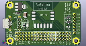
This board carries the ESP-M3 module.
The Gerbers (Yup... you can get your own boards pretty quick & cheap)
NOTE: If using PCBWAY for production, the size for these boards needs to be input as 61mm x 36.6. If you use a slightly different (slightly rounder) number, they will charge you a dollar to change it. Just so you know.
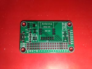
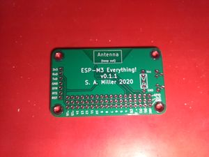
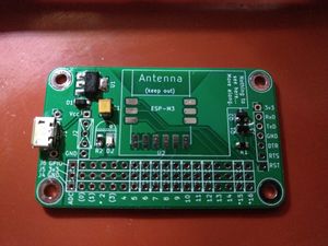
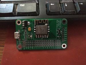
W00t! Boards are here!
0.17V on Vcc seems wrong...
Think I'll go ahead and suspect the connector isn't on there quite right. Real bitch to hand solder.
Feeding it 5V directly works just fine...
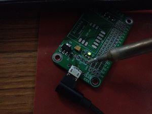
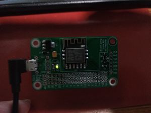
Just had to add flux & stick the tip of my iron under there to carefully reflow pin 1 of the USB connector.
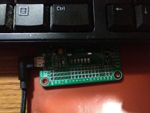
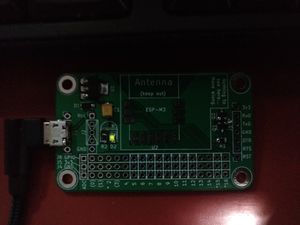
Notice that I had to take that picture with lots of shade so the LED would show up... :(
(10K at R2 may be a little bit of over-reaction to typical Chinese indicator LEDs...)
In fact, I tried 2K2 on the second board. This is also good...
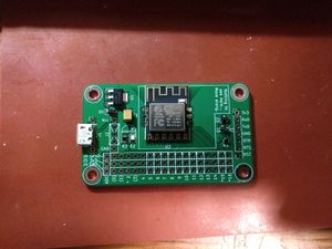
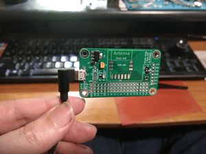
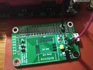
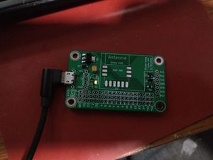
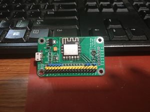
At this point, the board is fully populated.
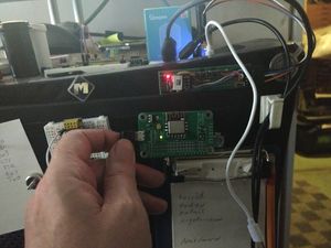
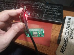
Not enough hands to catch the bootup blink of the M3 in the picture, but it did flash.
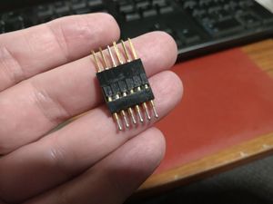
At this point, tomorrow evenings project is to mount this with a CH340 or CP2102 module to a protoboard & finish testing.
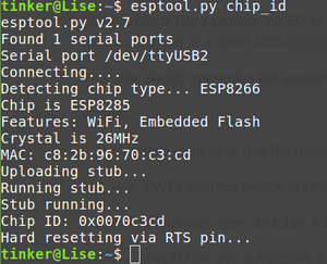
Well... Off by a day, but I built the programming adaptor.
Tho... I suppose it'd be an idea to actually flash something to it & fully prove the point.
So:
esptool.py erase_flash
Followed by:
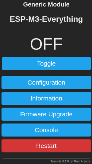
esptool.py write_flash -fs 1MB -fm dout 0x0 tasmota.bin
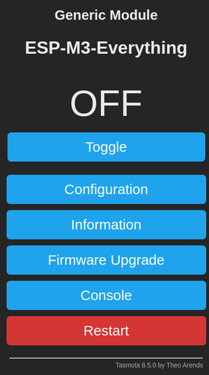
and...
At this point...
I do believe the appropriate expression is:
YIPPEE!
