Difference between revisions of "ESP8266 / ESP8285"
Jump to navigation
Jump to search
(→Notes) |
|||
| Line 7: | Line 7: | ||
*IO13 & IO16 don't seem usable for I2C... (at least under Tasmota...) | *IO13 & IO16 don't seem usable for I2C... (at least under Tasmota...) | ||
| + | |||
| + | === GPIO Pins === | ||
| + | {| class="wikitable" | ||
| + | |+ | ||
| + | !GPIO | ||
| + | !Input | ||
| + | !Output | ||
| + | !Boot State | ||
| + | !Notes | ||
| + | !01 | ||
| + | !M3 | ||
| + | !07 | ||
| + | !12 | ||
| + | !D1 mini | ||
| + | |- | ||
| + | |ADC0 | ||
| + | |'''Analog Input''' | ||
| + | |(not useable) | ||
| + | | | ||
| + | | | ||
| + | |X | ||
| + | |X | ||
| + | | | ||
| + | | | ||
| + | | | ||
| + | |- | ||
| + | |0 | ||
| + | |pulled up | ||
| + | |(caution) | ||
| + | | | ||
| + | |connected to FLASH button, boot fails if pulled LOW | ||
| + | | | ||
| + | | | ||
| + | | | ||
| + | | | ||
| + | | | ||
| + | |- | ||
| + | |1 | ||
| + | |'''TX pin''' | ||
| + | |(caution) | ||
| + | |'''HIGH''' | ||
| + | |debug output at boot, boot fails if pulled LOW | ||
| + | | | ||
| + | | | ||
| + | | | ||
| + | | | ||
| + | | | ||
| + | |- | ||
| + | |2 | ||
| + | |pulled up | ||
| + | |(caution) | ||
| + | |'''HIGH''' | ||
| + | |boot fails if pulled LOW | ||
| + | | | ||
| + | |on-board LED | ||
| + | | | ||
| + | | | ||
| + | |on-board LED | ||
| + | |- | ||
| + | |3 | ||
| + | |(caution) | ||
| + | |RX pin | ||
| + | |'''HIGH''' | ||
| + | | | ||
| + | | | ||
| + | | | ||
| + | | | ||
| + | | | ||
| + | | | ||
| + | |- | ||
| + | |4 | ||
| + | | | ||
| + | | | ||
| + | | | ||
| + | |often used as <code>SDA</code> (I2C) | ||
| + | |X | ||
| + | | | ||
| + | | | ||
| + | | | ||
| + | | | ||
| + | |- | ||
| + | |5 | ||
| + | | | ||
| + | | | ||
| + | | | ||
| + | |often used as <code>SCL</code> (I2C) | ||
| + | |X | ||
| + | |X | ||
| + | | | ||
| + | | | ||
| + | | | ||
| + | |- | ||
| + | |6 | ||
| + | | | ||
| + | | | ||
| + | | | ||
| + | |connected to the flash chip | ||
| + | |X | ||
| + | |X | ||
| + | |X | ||
| + | | | ||
| + | |X | ||
| + | |- | ||
| + | |7 | ||
| + | | | ||
| + | | | ||
| + | | | ||
| + | |connected to the flash chip | ||
| + | |X | ||
| + | |X | ||
| + | |X | ||
| + | | | ||
| + | |X | ||
| + | |- | ||
| + | |8 | ||
| + | | | ||
| + | | | ||
| + | | | ||
| + | |connected to the flash chip | ||
| + | |X | ||
| + | |X | ||
| + | |X | ||
| + | | | ||
| + | |X | ||
| + | |- | ||
| + | |9 | ||
| + | | | ||
| + | | | ||
| + | |'''HIGH''' | ||
| + | |connected to the flash chip | ||
| + | |X | ||
| + | |X | ||
| + | |X | ||
| + | | | ||
| + | |X | ||
| + | |- | ||
| + | |10 | ||
| + | | | ||
| + | | | ||
| + | |'''HIGH''' | ||
| + | |connected to the flash chip | ||
| + | |X | ||
| + | |X | ||
| + | |X | ||
| + | | | ||
| + | |X | ||
| + | |- | ||
| + | |11 | ||
| + | | | ||
| + | | | ||
| + | | | ||
| + | |connected to the flash chip | ||
| + | |X | ||
| + | |X | ||
| + | |X | ||
| + | | | ||
| + | |X | ||
| + | |- | ||
| + | |12 | ||
| + | | | ||
| + | | | ||
| + | | | ||
| + | |<code>SPI</code> (MISO) | ||
| + | |X | ||
| + | |X | ||
| + | | | ||
| + | | | ||
| + | | | ||
| + | |- | ||
| + | |13 | ||
| + | | | ||
| + | | | ||
| + | | | ||
| + | |<code>SPI</code> (MOSI) | ||
| + | |X | ||
| + | | | ||
| + | | | ||
| + | | | ||
| + | | | ||
| + | |- | ||
| + | |14 | ||
| + | | | ||
| + | | | ||
| + | | | ||
| + | |<code>SPI</code> (SCLK) | ||
| + | |X | ||
| + | | | ||
| + | | | ||
| + | | | ||
| + | | | ||
| + | |- | ||
| + | |15 | ||
| + | |pulled to GND | ||
| + | |(caution) | ||
| + | |'''LOW''' | ||
| + | |<code>SPI</code> (CS) | ||
| + | |||
| + | Boot fails if pulled HIGH | ||
| + | |X | ||
| + | |X | ||
| + | | | ||
| + | | | ||
| + | | | ||
| + | |- | ||
| + | |16 | ||
| + | |no interrupt | ||
| + | |no PWM or I2C support | ||
| + | |'''HIGH''' | ||
| + | |used to wake up from deep sleep | ||
| + | |X | ||
| + | | | ||
| + | | | ||
| + | | | ||
| + | | | ||
| + | |} | ||
==Modules== | ==Modules== | ||
Revision as of 23:00, 30 October 2020
Contents
Notes
- IO13 & IO16 don't seem usable for I2C... (at least under Tasmota...)
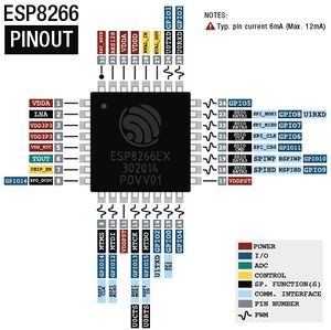
GPIO Pins
| GPIO | Input | Output | Boot State | Notes | 01 | M3 | 07 | 12 | D1 mini |
|---|---|---|---|---|---|---|---|---|---|
| ADC0 | Analog Input | (not useable) | X | X | |||||
| 0 | pulled up | (caution) | connected to FLASH button, boot fails if pulled LOW | ||||||
| 1 | TX pin | (caution) | HIGH | debug output at boot, boot fails if pulled LOW | |||||
| 2 | pulled up | (caution) | HIGH | boot fails if pulled LOW | on-board LED | on-board LED | |||
| 3 | (caution) | RX pin | HIGH | ||||||
| 4 | often used as SDA (I2C)
|
X | |||||||
| 5 | often used as SCL (I2C)
|
X | X | ||||||
| 6 | connected to the flash chip | X | X | X | X | ||||
| 7 | connected to the flash chip | X | X | X | X | ||||
| 8 | connected to the flash chip | X | X | X | X | ||||
| 9 | HIGH | connected to the flash chip | X | X | X | X | |||
| 10 | HIGH | connected to the flash chip | X | X | X | X | |||
| 11 | connected to the flash chip | X | X | X | X | ||||
| 12 | SPI (MISO)
|
X | X | ||||||
| 13 | SPI (MOSI)
|
X | |||||||
| 14 | SPI (SCLK)
|
X | |||||||
| 15 | pulled to GND | (caution) | LOW | SPI (CS)
Boot fails if pulled HIGH |
X | X | |||
| 16 | no interrupt | no PWM or I2C support | HIGH | used to wake up from deep sleep | X |
Modules
- ESP-01
- ESP-M3
- ESP-07
- ESP-12
- Getting Started with the ESP8266 ESP-12 (looks to apply to ESP-07 also)
- LOLIN D1 mini
Sonoff
Most (all?) of these are basically ESP8266 or ESP8265 controlled relays
Firmware
ESP8266 WiFi Connection manager
Original?
Tasmota
Espruino
ESPurna
ESP-MQTT
ESP-go
NodeMcu
ESP Easy
ESPHelper
WLED
- Home
- Many bugs seem to appear with version changes...
- 0.8.6 seems functional on my D1 Minis. (Tho it self-reports as 0.8.4)
- Many bugs seem to appear with version changes...
Setting up Modules
Information Links
- A Beginner's Guide to the ESP8266
- Espressif Systems (manufacturer)
- ESP8266 Module Family
- Different types of ESP8266 module
- On Wikipedia
- ESP8266 Serial WIFI Module (ITEAD Wiki)
- Official Forum
- ESP8266 Community Forum
- Espruino Software Reference
- Kolban’s book on the ESP8266
- ESP8266EX Pinouts and Connections
Usage Links
- ESP8266 WiFi Module for Dummies
- ESP8266 Serial Interface to WiFi
- Simple Arduino Web Server on ESP-07/ESP-12 Tutorial
- Cheap and Easy WiFi (IoT) Tutorial Part 1 - ESP8266 Setup/Intro
- Cheap and Easy WiFi (IoT) Tutorial Part 2 - ESP8266 Arduino Code
- ESP8266 Native
- Control ESP8266 over the internet (from anywhere)
- Esp8266 firmware update
- WiFi / Internet Controlled Relays using ESP8266 - Quick, 30 minutes IoT project
- Telnet server example
Programming
- How to wire an ESP07/12 for programming
- The Simple Guide to Flashing Your ESP8266 Firmware
- Upload sketch to the ESP8266 (ESP-07/ESP-12) using Arduino IDE
- ESP8266 as Arduino
- Update the Firmware in Your ESP8266 Wi-Fi Module
- ESP8266 core for Arduino
Hardware
Ethernet
- ENC28J60 - ETHERNET CABLE CONNECTION TO ESP8266 (ESPHTTPD)
- Ethernet Controller Discovered in the ESP8266
- Wired Networking For The ESP8266
& More
- ESP8266 Power Saving
Projects
- Virtual serial port tunnel (to use with ESP-Link)
- Possibly useful for connecting serial devices over WiFi
- ESP-Link
- WiFi Plant Watering ESP8266
- WIFI Battery Monitor System - ESP8266
- Using an esp8266 arduino to control a relay using home-assistant
- ESP8266 Wireless Toilet Usage Indicator (Smart Home)
- Free Dynamic DNS Server with Esp8266 and OSD FOSCAM Webcam Interface
- ESP8266 Automatic Router Restart
- ESP8266 BASIC IoT Light
- MASLOW: an Open WiFi Detector with ESP8266
- ESP8266 - $5 internet connected switch
- Wifi Relay With ESP8266
- ESP8266 Internet Alarm
- ESP8266 Wifi Timer Switch for AC Loads
- Wifi enabled 8×64 pixel LED matrix display
- ESP8266 GMail sender
- Very Cheap/Simple WiFi Shield for Arduino and microprocessors
- ESP8266 Weather Widget
- ESP8266 - $5 internet connected switch
- Wifi Dot Matrix Sign
- ESP Weather Forecaster
- Clear Sky Indicator for Astronomy! (Another ESP Weather Forcaster)
- Kevin Darrahs take on the idea...
- Some bunos ideas to look into, like EEPROM wear leveling
