Difference between revisions of "IoT - ESP-M3 Everything!"
Jump to navigation
Jump to search
| Line 21: | Line 21: | ||
[[File:Nope.jpg|none|thumb]] | [[File:Nope.jpg|none|thumb]] | ||
0.17V on Vcc seems wrong... | 0.17V on Vcc seems wrong... | ||
| + | |||
| + | Think I'll go ahead and suspect the connector isn't on there quite right. Real bitch to hand solder. | ||
| + | [[File:Semi-w00t.jpg|none|thumb]] | ||
| + | Semi-w00t... Feeding it 5V directly works just fine... | ||
| + | |||
| + | (tho 10K at R2 may be a little bit of over-reaction to typical Chinese indicator LEDs...) | ||
Revision as of 00:05, 15 October 2020
This is the one that started it all...
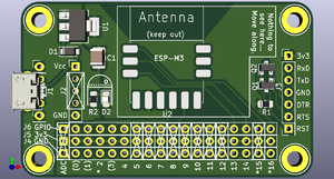
The Gerbers (Yup... you can get your own boards pretty quick & cheap)
(Still working on this page... Been a long day...)
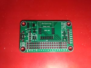
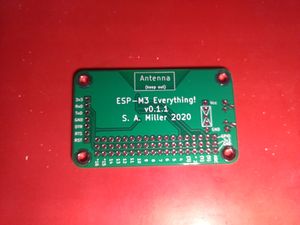
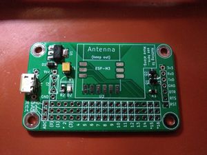
W00t! Boards are here!
This is gonna be a little bit fiddly...
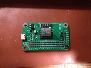
Here's the first attempt at the truly fiddly bits...
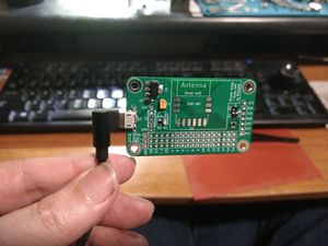
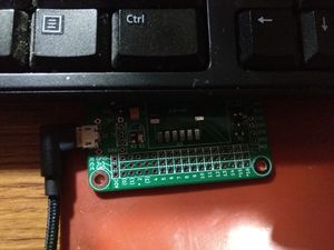
Shall we see if it lives?
Nope :(
0.17V on Vcc seems wrong...
Think I'll go ahead and suspect the connector isn't on there quite right. Real bitch to hand solder.
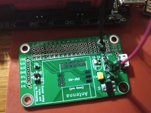
Semi-w00t... Feeding it 5V directly works just fine...
(tho 10K at R2 may be a little bit of over-reaction to typical Chinese indicator LEDs...)
