Difference between revisions of "ESP-07"
Jump to navigation
Jump to search
(Created page with " {| width="589" cellspacing="1" cellpadding="1" border="1" |+ Top of Module |- ! scope="col" style="width: 93.6667px" | Label ! scope="col" style="width: 1px" | Pin # ! scope=...") |
|||
| Line 38: | Line 38: | ||
| style="text-align: center; vertical-align: middle; width: 1px" | 6 | | style="text-align: center; vertical-align: middle; width: 1px" | 6 | ||
| style="text-align: center; vertical-align: middle" | 11 | | style="text-align: center; vertical-align: middle" | 11 | ||
| − | | GPIO2 (alt TX in bootloader mode) | + | | GPIO2 (alt TX in bootloader mode) (on-board blue LED) |
|- | |- | ||
| style="width: 93.6667px" | GPIO13 | | style="width: 93.6667px" | GPIO13 | ||
| Line 86: | Line 86: | ||
| GPIO14 | | GPIO14 | ||
|- | |- | ||
| − | | GPIO2 (alt TX in bootloader mode) | + | | GPIO2 (alt TX in bootloader mode) (on-board blue LED) |
| style="text-align: center; vertical-align: middle; width: 1px" | 11 | | style="text-align: center; vertical-align: middle; width: 1px" | 11 | ||
| style="text-align: center; vertical-align: middle" | 6 | | style="text-align: center; vertical-align: middle" | 6 | ||
Revision as of 15:33, 9 November 2020
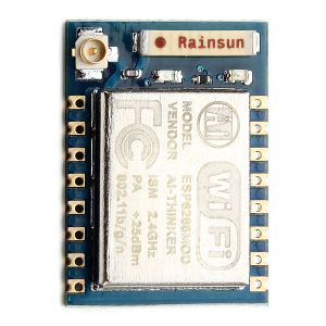
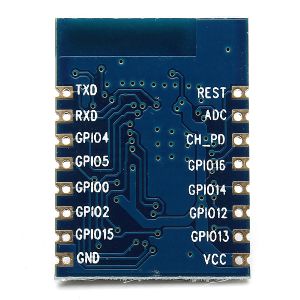
ESP8266 ESP-07 Remote Serial Port WIFI Transceiver Wireless Module

