Difference between revisions of "MCU - Display - TFT"
Jump to navigation
Jump to search
(Created page with "===ILI9341 SPI TFT LCD Display Touch Panel=== [https://www.banggood.com/2_8-Inch-ILI9341-240x320-SPI-TFT-LCD-Display-Touch-Panel-SPI-Serial-Port-Module-p-1206782.html 2.8 Inch...") |
(→Pins) |
||
| (10 intermediate revisions by the same user not shown) | |||
| Line 5: | Line 5: | ||
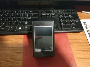
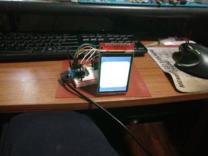
[[File:TFT-1st Test.jpg|thumb|link=Special:FilePath/TFT-1st_Test.jpg]] | [[File:TFT-1st Test.jpg|thumb|link=Special:FilePath/TFT-1st_Test.jpg]] | ||
[[File:TFT-Testing.mp4|thumb|link=Special:FilePath/TFT-Testing.mp4]] | [[File:TFT-Testing.mp4|thumb|link=Special:FilePath/TFT-Testing.mp4]] | ||
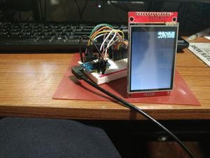
| + | [[File:TFT-Tasmotized.jpg|thumb|link=Special:FilePath/TFT-Tasmotized.jpg]] | ||
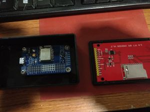
| + | [[File:TFT-InaBox.jpg|thumb|link=Special:FilePath/TFT-InaBox.jpg]] | ||
| + | [[File:TFT-NotWired.jpg|thumb|link=Special:FilePath/TFT-NotWired.jpg]] | ||
| + | [[File:TFT-Aaarrrggg.jpg|thumb|link=Special:FilePath/TFT-Aaarrrggg.jpg]] | ||
| + | [[File:TFT-FingersCrossed.jpg|thumb|link=Special:FilePath/TFT-FingersCrossed.jpg]] | ||
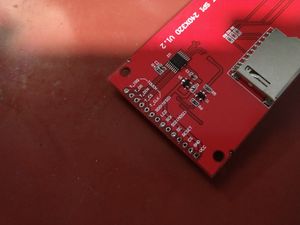
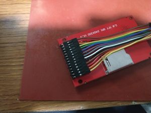
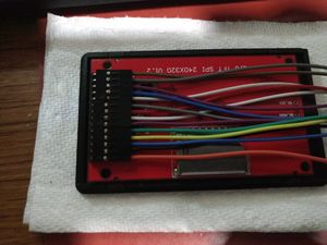
| + | [[File:TFT-Connections.jpg|thumb|link=Special:FilePath/TFT-Connections.jpg]] | ||
| + | [[File:TFT-Whew.jpg|thumb|link=Special:FilePath/TFT-Whew.jpg]] | ||
| + | [[File:TFT-StillWorks.jpg|thumb|link=Special:FilePath/TFT-StillWorks.jpg]] | ||
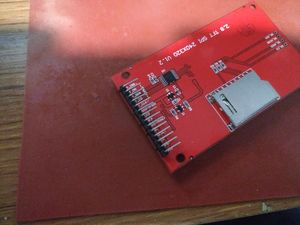
| + | [[File:TFT-Wired.jpg|thumb|link=Special:FilePath/TFT-Wired.jpg]] | ||
====Pins==== | ====Pins==== | ||
| − | {| class="wikitable" | + | {| class="wikitable sortable" |
|+ | |+ | ||
! | ! | ||
| Line 16: | Line 25: | ||
|- | |- | ||
! | ! | ||
| + | !Label | ||
!Signal | !Signal | ||
| − | ! | + | !{colour} |
| − | |||
!NodeMCU | !NodeMCU | ||
!Actual | !Actual | ||
|- | |- | ||
| − | | | + | |14 |
|T_IRQ | |T_IRQ | ||
| | | | ||
| − | | | + | |BRN |
|D1 | |D1 | ||
|GPIO5 | |GPIO5 | ||
|- | |- | ||
| − | | | + | |13 |
|T_DO | |T_DO | ||
| − | | | + | |(MISO) |
| − | | | + | |GRY |
|D6 | |D6 | ||
|GPIO12 | |GPIO12 | ||
|- | |- | ||
| − | | | + | |12 |
|T_DIN | |T_DIN | ||
| − | | | + | |(MOSI) |
| − | | | + | |VIO |
|D7 | |D7 | ||
|GPIO13 | |GPIO13 | ||
|- | |- | ||
| − | | | + | |11 |
|T_CS | |T_CS | ||
| − | | | + | |SPI select |
| − | | | + | |BLU (t) |
| − | | | + | |D8 |
| − | | | + | |GPIO15 |
|- | |- | ||
| − | | | + | |10 |
|T_CLK | |T_CLK | ||
| − | | | + | |SPI clk |
| − | | | + | |WHI |
|D5 | |D5 | ||
|GPIO14 | |GPIO14 | ||
| Line 64: | Line 73: | ||
| | | | ||
|- | |- | ||
| − | | | + | |9 |
|SDO(MISO) | |SDO(MISO) | ||
| − | | | + | |(MISO) |
| − | | | + | |GRY |
|D6 | |D6 | ||
|GPIO12 | |GPIO12 | ||
|- | |- | ||
| − | | | + | |8 |
|LED | |LED | ||
| − | | | + | |pwr LED |
| − | | | + | |RED |
| − | |VCC | + | |<u>VCC</u> |
| − | | | + | |? |
|- | |- | ||
| − | | | + | |7 |
|SCK | |SCK | ||
| − | | | + | |SPI clk |
| − | | | + | |WHI |
|D5 | |D5 | ||
|GPIO14 | |GPIO14 | ||
|- | |- | ||
| − | | | + | |6 |
|SDI(MOSI) | |SDI(MOSI) | ||
| − | | | + | |(MOSI) |
| − | | | + | |VIO |
|D7 | |D7 | ||
|GPIO13 | |GPIO13 | ||
|- | |- | ||
| − | | | + | |5 |
| − | | | + | |D/C |
| − | | | + | |Data/Cmnd |
| − | | | + | |GRN |
|D4 | |D4 | ||
|GPIO2 | |GPIO2 | ||
|- | |- | ||
| − | | | + | |4 |
|RESET | |RESET | ||
| − | | | + | |{D3} |
| − | | | + | |YEL |
| − | |VCC | + | |VCC {D3} |
| − | |3v3 | + | |3v3 {GPIO0} |
|- | |- | ||
| − | | | + | |3 |
|CS | |CS | ||
| − | | | + | |SPI select |
| − | | | + | |BLU (s) |
| − | | | + | |D2 |
| − | | | + | |GPIO4 |
|- | |- | ||
| − | | | + | |2 |
|GND | |GND | ||
| − | | | + | |pwr GND |
| − | | | + | |BLK |
|GND | |GND | ||
|GND | |GND | ||
|- | |- | ||
| − | | | + | |1 |
|VCC | |VCC | ||
| − | | | + | |pwr 3V3 |
| − | | | + | |ORA |
|VCC | |VCC | ||
|3v3 | |3v3 | ||
| Line 129: | Line 138: | ||
(Why in hell do dev-board makers, & Arduino for that matter, think changing the actual GPIO numbers to some random shit was a good idea???) | (Why in hell do dev-board makers, & Arduino for that matter, think changing the actual GPIO numbers to some random shit was a good idea???) | ||
| + | |||
| + | ====Firmware==== | ||
| + | Seems to work pretty good with Tasmota-Display. | ||
====Links==== | ====Links==== | ||
Latest revision as of 00:47, 1 July 2021
ILI9341 SPI TFT LCD Display Touch Panel
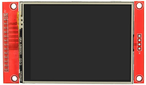
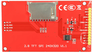
2.8 Inch ILI9341 240x320 SPI TFT LCD Display Touch Panel SPI Serial Port Module
Pins
| Nailbuster Examples | |||||
|---|---|---|---|---|---|
| Label | Signal | {colour} | NodeMCU | Actual | |
| 14 | T_IRQ | BRN | D1 | GPIO5 | |
| 13 | T_DO | (MISO) | GRY | D6 | GPIO12 |
| 12 | T_DIN | (MOSI) | VIO | D7 | GPIO13 |
| 11 | T_CS | SPI select | BLU (t) | D8 | GPIO15 |
| 10 | T_CLK | SPI clk | WHI | D5 | GPIO14 |
| 9 | SDO(MISO) | (MISO) | GRY | D6 | GPIO12 |
| 8 | LED | pwr LED | RED | VCC | ? |
| 7 | SCK | SPI clk | WHI | D5 | GPIO14 |
| 6 | SDI(MOSI) | (MOSI) | VIO | D7 | GPIO13 |
| 5 | D/C | Data/Cmnd | GRN | D4 | GPIO2 |
| 4 | RESET | {D3} | YEL | VCC {D3} | 3v3 {GPIO0} |
| 3 | CS | SPI select | BLU (s) | D2 | GPIO4 |
| 2 | GND | pwr GND | BLK | GND | GND |
| 1 | VCC | pwr 3V3 | ORA | VCC | 3v3 |
(Why in hell do dev-board makers, & Arduino for that matter, think changing the actual GPIO numbers to some random shit was a good idea???)
Firmware
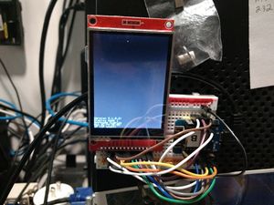
Seems to work pretty good with Tasmota-Display.
Links
- 2.8″ TOUCH LCD SPI FOR ESP8266 (NODEMCU)
- Code seems to work...
- Interfacing ESP8266 NodeMCU with ILI9341 TFT display
- Code seems to work...
- Once you add
#include <Arduino.h>and#include <SPI.h> - Aside from tripping over the WDT... :(
- tft.fillRect() seems to kick the watchdog.
- testFilledCircles() kicks the watchdog instead of returning.
- SOLUTION: Add
ESP.wdtFeed();immediately before most calls to the shitty Adafruit library functions.
- Once you add
- Code seems to work...
