Difference between revisions of "ESP32"
Jump to navigation
Jump to search
| (3 intermediate revisions by the same user not shown) | |||
| Line 723: | Line 723: | ||
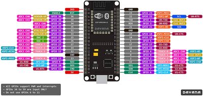
*[[File:ESP32 FM-DevKit PinOut.jpg|thumb|FM-DevKit]]The GOOD ones currently on hand are clones of the FM-DevKit | *[[File:ESP32 FM-DevKit PinOut.jpg|thumb|FM-DevKit]]The GOOD ones currently on hand are clones of the FM-DevKit | ||
| + | ** UART: CP2102 | ||
**I have 2 | **I have 2 | ||
*[[File:D1 mini ESP32 pinout.png|thumb|Mini D1 ESP32]]The ANNOYING one on hand is a "mini D1 ESP32" (Wemos clone...) | *[[File:D1 mini ESP32 pinout.png|thumb|Mini D1 ESP32]]The ANNOYING one on hand is a "mini D1 ESP32" (Wemos clone...) | ||
| + | ** UART: CP2104 | ||
**As shipped, it has a VERY bad habit of detecting a brownout instead of starting WiFi upon reboot. Then it reboots itself & carries on. | **As shipped, it has a VERY bad habit of detecting a brownout instead of starting WiFi upon reboot. Then it reboots itself & carries on. | ||
| − | **SOLUTION: | + | **'''SOLUTION:''' 100 μF or bigger cap across 3v3 |
| + | **'''Well... NOPEish... The built-in regulator is pretty much shit.''' connect anything to it & it still fails to properly boot. | ||
*The 3rd type is from KeyeStudio & seems to be another FM-DevKit clone | *The 3rd type is from KeyeStudio & seems to be another FM-DevKit clone | ||
| + | ** UART: CP2102 | ||
| + | |||
*Interesting: [https://m5stack.com/ M5Stack] | *Interesting: [https://m5stack.com/ M5Stack] | ||
*[https://hackaday.com/2019/07/09/new-part-day-the-15-esp32-with-cellular/ NEW PART DAY: THE $15 ESP32 WITH CELLULAR] | *[https://hackaday.com/2019/07/09/new-part-day-the-15-esp32-with-cellular/ NEW PART DAY: THE $15 ESP32 WITH CELLULAR] | ||
Latest revision as of 00:19, 10 August 2021
Contents
Notes
GPIO Pins
| GPIO | Arduino | Input | Output | Boot State | Strapping | Cap Touch | ADC | DAC | RTC | Notes | 1 | 2 | 3 | ||
|---|---|---|---|---|---|---|---|---|---|---|---|---|---|---|---|
| 0 | (caution) | (caution) | T1 | ADC2_CH1 | RTC_GPIO11 |
|
|||||||||
| 1 | TX pin | (caution) | HIGH |
|
|||||||||||
| 2 | T2 | ADC2_CH2 | RTC_GPIO12 |
|
|||||||||||
| 3 | (caution) | RX pin | HIGH |
|
|||||||||||
| 4 | T0 | ADC2_CH0 | RTC_GPIO10 | ||||||||||||
| 5 | HIGH | must be HIGH? | VSPI CS |
|
|||||||||||
| 6 | no | no |
|
||||||||||||
| 7 | no | no |
|
||||||||||||
| 8 | no | no |
|
||||||||||||
| 9 | no | no |
|
||||||||||||
| 10 | no | no |
|
||||||||||||
| 11 | no | no |
|
||||||||||||
| 12 | (caution) | must be LOW? | T5 | ADC2_CH5 | RTC_GPIO15 | HSPI MISO |
|
||||||||
| 13 | T4 | ADC2_CH4 | RTC_GPIO14 | HSPI MOSI | |||||||||||
| 14 | T6 | ADC2_CH6 | RTC_GPIO16 | HSPI CLK |
|
||||||||||
| 15 | must be HIGH? | T3 | ADC2_CH3 | RTC_GPIO13 | HSPI CS |
|
|||||||||
| 16 | |||||||||||||||
| 17 | |||||||||||||||
| 18 | VSPI CLK | ||||||||||||||
| 19 | VSPI MISO | ||||||||||||||
| 20 | |||||||||||||||
| 21 | I2C SDA | ||||||||||||||
| 22 | I2C SCL | ||||||||||||||
| 23 | VSPI MOSI | ||||||||||||||
| 24 | |||||||||||||||
| 25 | ADC2_CH8 | DAC1 | RTC_GPIO6 | ||||||||||||
| 26 | ADC2_CH9 | DAC2 | RTC_GPIO7 | ||||||||||||
| 27 | T7 | ADC2_CH7 | RTC_GPIO17 | ||||||||||||
| 28 | |||||||||||||||
| 29 | |||||||||||||||
| 30 | |||||||||||||||
| 31 | |||||||||||||||
| 32 | T9 | ADC1_CH4 | RTC_GPIO9 | ||||||||||||
| 33 | T8 | ADC1_CH5 | RTC_GPIO8 | ||||||||||||
| 34 | no | ADC1_CH6 | RTC_GPIO4 | ||||||||||||
| 35 | no | ADC1_CH7 | RTC_GPIO5 | ||||||||||||
| 36 | no | ADC1_CH0 | RTC_GPIO0 | ||||||||||||
| 37 | ADC1_CH1 | ||||||||||||||
| 38 | ADC1_CH2 | ||||||||||||||
| 39 | no | ADC1_CH3 | RTC_GPIO3 |
Modules
- The GOOD ones currently on hand are clones of the FM-DevKit
- UART: CP2102
- I have 2
- The ANNOYING one on hand is a "mini D1 ESP32" (Wemos clone...)
- UART: CP2104
- As shipped, it has a VERY bad habit of detecting a brownout instead of starting WiFi upon reboot. Then it reboots itself & carries on.
- SOLUTION: 100 μF or bigger cap across 3v3
- Well... NOPEish... The built-in regulator is pretty much shit. connect anything to it & it still fails to properly boot.
- The 3rd type is from KeyeStudio & seems to be another FM-DevKit clone
- UART: CP2102
- Interesting: M5Stack
- NEW PART DAY: THE $15 ESP32 WITH CELLULAR
ESP & Wired Ethernet
Firmware
Information Links
ESP32 pin allocation spreadsheet


